Wednesday, May 26, 2010

Part 0007 continues

To get this far, I have written 14 NC files. They are:
001 6mm one quarter face milling
002 6mm counterbores
003 6mm big hole
004 3mm small holes
101 6mm wood area
102 6mm rectangle hole
102b 6mm wood area with island
103 6mm outside profile
104 3mm holes
201 6mm wood area
202 6mm right holes
203 6mm top right profile
204 6mm bottom right profile
205 6mm sub table

No super glue was used. I used double sided carpet tape for the facing operations.
I am using an adjustable spanner each time I change tool, because I don't have a 15mm spanner.
I don't have any safety spectacles.
Today I ordered both these things online as a reward for my hard work.

Part 0007 toolpath

Sitting here waiting for this to be cut on the machine next door. I thought I'd show you the toolpath generated by HeeksCNC 0.13.0 on Windows Vista.
Click on the picture to see it full size.

Part 0007 - wood screw

Here I am clamping by screwing into the wood. I drilled a pilot hole for the wood screw with a hand-held electric drill. I tightened the wood screw until I could hear the wood cracking.
But still I was not clamped tightly enough. In the picture you can see that the tool path has veered to the left as the Delrin has been forced to the right. Fortunately the part is not scrap.
I will re-cut the wood area with an island for the rectangular hole to sit in and try again.

Tuesday, May 25, 2010

Part 0007

Part 0007 is a bigger job than I first thought. I had not noticed that the middle part of it is bigger in Y than my machine can handle. I will need to tackle it in many separate operations. The first job is to face mill it to the right thickness. I have programmed a pocketing operation to do a bit more than a quarter of it. I am using carpet tape to stick it down to the metal of the machine table.

Friday, May 21, 2010

Part 0008 finished


What happened to Part 0007? Apparently it needs another hole in it, so I am waiting for the new CAD file before I start.
Part 0008 was interesting, because it introduced me to the vice and therefore the dial indicator.
The old dial indicator that dad gave me needed moving a few times before it loosened up and would spring back by itself. It is marked in increments of 0.001 inches.

Wednesday, May 19, 2010

Part 0006 finished

I made these two.
This concave corner was drawn as a perfect corner. I have made it with a 3mm radius. I hope this is OK. Also the internal corners I made with a 3mm radius instead of the 2mm radius they were drawn with, so I could use my favourite 6mm slot cutter.
I am not so happy with the holes at the end. I machined a piece of wood with a hole in, as a guide piece to fit the end, then I drilled them on dad's pillar drill. The depth is pretty accurate, but the position is not good. If X is the 100mm side and Y is the 10mm side, then the position is accurate to X 0.02 on each of them, which I am happy with. But on one of them the Y is 0.20 wrong and on the second one Y is 0.10 wrong. For the second one, I put a clamp across the wood, which seems to have helped. I believe I need to use a better material as the guide. I should use an off-cut of delrin. The holes were drawn 6.4mm diameter. I used a 6mm drill and the hole ended up about 5.9mm diameter. I don't have a 6.5mm drill. I will buy a box of drills which include a 6.5mm drill and redrill them with a delrin guide, later.

Tuesday, May 18, 2010

Part 006 one almost finished


This one is done, except for a hole in the end facing us. I need another one like this, though.

Monday, May 17, 2010

Part 0006 started


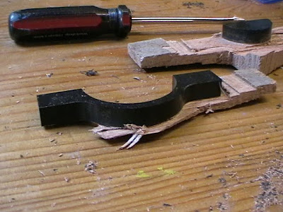
This part will require machining in two different setups. First I machined some counter-bored holes in a piece of wood ( using the Profile operation ) and finished them with Dad's pillar drill. I bolted this on to the table using the t-slots. I machined an area flat on the wood. I super-glued the Delrin to the wood. I am doing some profile operations with 6mm slot cutter. Unfortunately I forgot to check that the Y-axis had enough travel in the position I placed it. It hit the limit while rapiding to the outside profile. The part is not scrap. I will need to do it again, but machine an area in the wood with an island left standing in the middle to locate the part.

Part 0005 done

Saturday, May 15, 2010

Dialog pictures

I extended the properties window to be able to have a different window. This can be in addition to or instead of the property grid. My example for cuboid just makes a window with a picture, but I hope to make some windows with controls ( edits, radio buttons, pictures, list boxes ).

Thursday, May 13, 2010

Part 0005 first side OK


This works well. It is a bit labourious having to saw away all the wood, so it is flexible enough to peel off the Delrin, but worth it. Leaving 0.1mm on the depth is always a good idea. It doesn't take long to sand it to exactly the depth I want.

Part 0005 super glue

I think carpet tape would be too inaccurate. Also I don't have any.
Super glue seems to stick Delrin to the wood strongly enough. Also, I can remove the piece from the wood with my pen-knife. Now, can I remove the super glue with hot soapy water and a sponge?...

Leaving it to soak in the washing up bowl...

No. But I can sand it off and nobody needs to know it was there. I'll leave a little bit extra on the face machining depth, so I can sand it down to the required thickness anyway.

Part 0005 attempt

A daring attempt to not waste material. I wanted to do this one without needing tags.
It seems to go wrong on the above picture, where the two clamps can't stop the top edge lifting up a bit.The underneath of the arch seems to join perfectly, so the lifting edge went back to where it was when I moved the clamps. I might try clampless machining. If super glue works well enough, it might be worth clamping the Delring to the wood with super glue.

Part 0004 finished

I made 2 more of these yesterday afternoon and I made 3 more of them this morning, so that is the 6 required.
With my method of clamping on to a sacrificial piece of hardwood, there are inaccuracies in thickness of the parts. If I clamp tighter, I get a thicker piece. Most of these pieces are between 9.96mm and 10.02 at the edges and about 9.85 to 9.95 near the middle ( depending which part you measure ), because of the way the piece is bending when clamped. But one part is about 9.88 all over, where I didn't clamp it so hard ( to try to reduce bending ). I could improve this, by using some aluminium to act as the sub-table, but this would make everything more expensive. I think these are meant to be fairly low cost parts. I will try clamping more gently for the facing operation, but adding 0.1mm to the programmed depth.

Tuesday, May 11, 2010

Part 0004


I made Part 0004 correct, first time. There are 6 in total wanted of these. I got the chamfer to within 0.1mm of what I wanted, I think; it's hard to measure the chamfer. The subsequent copies should be more relaxing to make. There are no tags on this part. I cut the outside profile in two separate operations, so I could remove two of my four clamps and replace them to get to every part of the profile. I put my fingers on the part as it was being cut to catch the piece of scrap that falls off and to damp vibrations.

Part 0003

I made Part 0003 correct, first time. I was able to re-use some of the operations from Part 0002.

This video shows the rough profile pass for the outside shape, done in two steps of 5mm.

Monday, May 10, 2010

Part 0002 finished

I did Part 0002 again with no mistakes.
The chamfer is about 0.2mm under size. I don't think this will be a problem.

Thursday, May 6, 2010

Part 0002 again


Only one mistake, this time. The chamfer was too big. I worked out what I did wrong. I wanted to offset the path 1mm from the part, so I told the software it was using a 1mm slot drill. I should have told it it was a 2mm slot drill. The chamfer is 3.8mm instead of 3mm. I left on 0.2mm for safety, but it was not enough.

Part 0002


I am making another part using HeeksCNC 0.13.0 and my Sieg KX1.
I made several mistakes and the part is scrap, but I didn't break any tools.
Mistake 1: The clamps were not far enough from the toolpath. I loosened one clamp and moved it and retightened it during cutting. This let the part lift up a little and I cut too deep. I should have pressed STOP, then moved the clamp, then restarted the operation.
Mistake 2: I zeroed the Z of the chamfer tool assuming it comes to a sharp point, but it has a small flat. So the chamfer was cut too big.
Mistake 3: I saw 5 holes and assumed they were all the same size, but some of them were smaller.
I will try again with no mistakes.